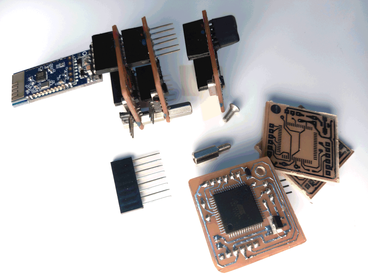
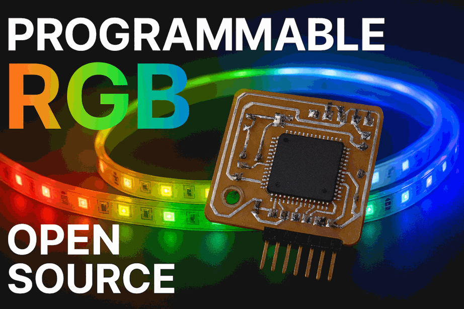
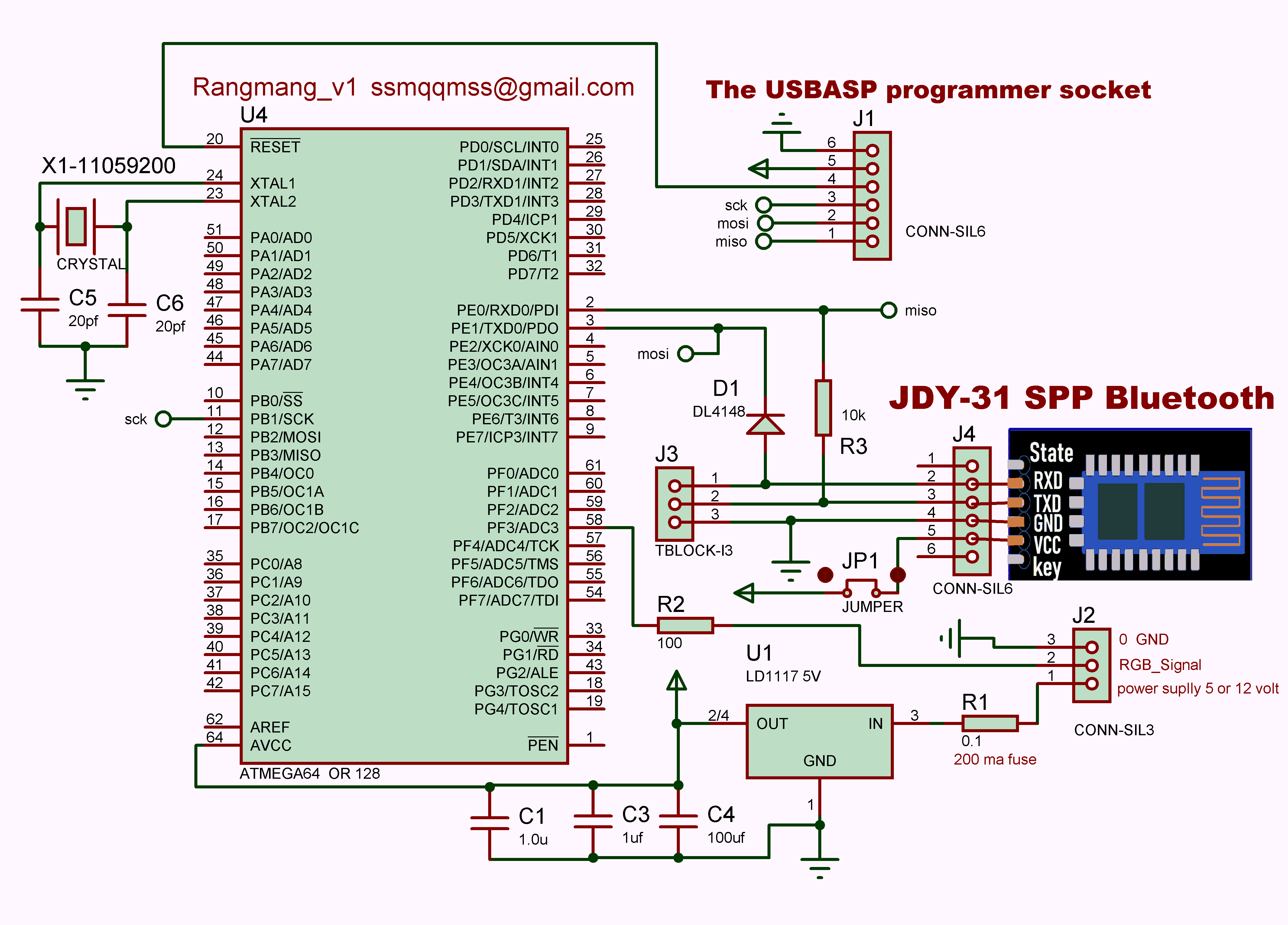
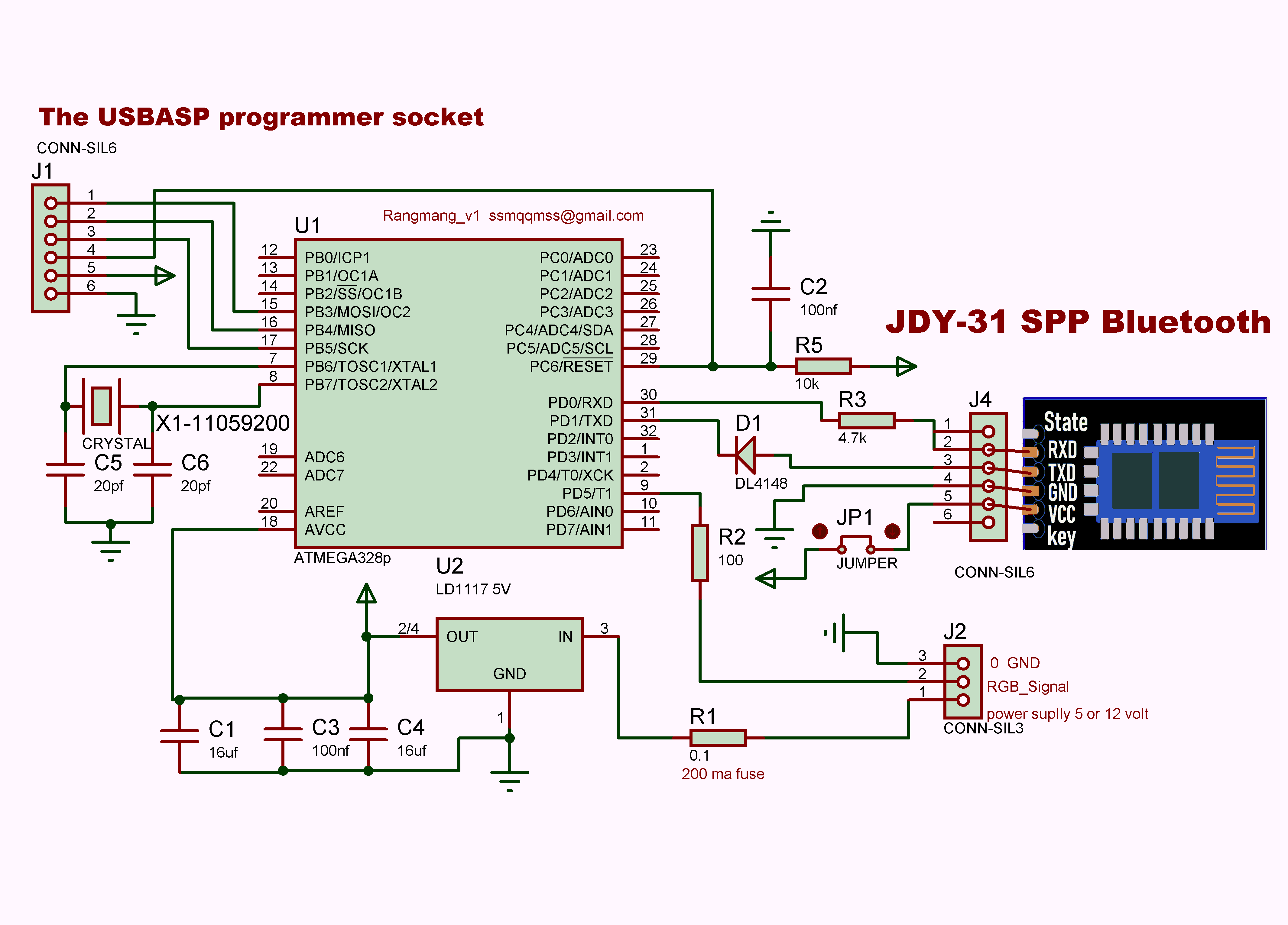
RANGMANG is an RGB controller based on the ATmega128 microcontroller, Programmed with serial communication.
The following table introduces various LED strips and their specifications:
| LED Strip Model | Operating Voltage | Control Type | Addressable | Special Features |
|---|---|---|---|---|
| WS2811 | 12V | Digital | Yes | Suitable for long strips |
| WS2812B | 5V | Digital | Yes | Built-in chip in each LED |
| WS2813 | 5V | Digital | Yes | Resistant to data line failure |
| WS2815 | 12V | Digital | Yes | Industrial-grade, low voltage drop |
| SK6812 | 5V | Digital | Yes | Supports RGBW (white channel) |
| SK9822 | 5V | Digital | Yes | High-speed, similar to APA102 |
| APA102 | 5V | Digital (Clock + Data) | Yes | Fast animations, dual-wire control |
| TM1814 | 12V | Digital | Yes | RGBW, high-power applications |
Official download link for USBasp Programmer: You can find complete files and information about the USBasp programmer on the developer's official website: fischl.de/usbasp.
This configuration defines how the RANGMANG module controls LED dance modes. Each row encodes the following parameters (ADRGBSEM format)
| A (Channel) | D (Mode) | R (Red) | G (Green) | B (Blue) | S (Dance Time 1) | E (Dance Time 2) | M (Pixel Count) |
|---|---|---|---|---|---|---|---|
| A1 | D12 | R251 | G251 | B251 | S1 | E1 | M128 |
| A (Channel) | D (Mode) | R (Red) | G (Green) | B (Blue) | S (Start Pixel) | E (End Pixel) | M (Memory Slot) |
|---|---|---|---|---|---|---|---|
| A1 | D0 | R200 | G50 | B100 | S1 | E120 | M10 |
If the module is used individually, connect the Bluetooth power jumper.

If the modules are used in parallel, only connect the jumper for the module linked to Bluetooth and disconnect the rest.

Install a 5V regulator for 12V LED strips; for 5V LED strips, no regulator is needed.

Use a single wire to solder and connect the input and output pins of the regulator directly on the board.
' Inputs format: ADRGBSEM (Leading zeros are optional)
' Example: A1D0R0G0B0S0E0M0
' A1 TO A98    FOR ADDRESS MODULE   A99 FOR ALL
' IF D0 THEN SOLID COLOR
' R: 0 TO 255   RED COLOR
' G: 0 TO 255   GREEN COLOR
' B: 0 TO 255   BLUE COLOR
' S: 0 TO 999   RGB STRIP START POSITION FOR COLORED PIXEL
' E: 0 TO 999   RGB STRIP END POSITION FOR COLORED PIXEL
' M: 0 TO 98    M0 WITHOUT MEMORY SAVE   M1 TO M98 SAVE SLOT MEMORY

' IF D1 TO D55   DANCE
' D99   FOR RANDOM SELECT D1 TO D55 DANCE
' R: 0 TO 250   RED COLOR   251 TO 255 FOR RANDOM RED COLOR
' G: 0 TO 250   GREEN COLOR   251 TO 255 FOR RANDOM GREEN COLOR
' B: 0 TO 250   BLUE COLOR   251 TO 255 FOR RANDOM BLUE COLOR
' S: 0 TO 999   RGB STRIP FIRST DELAY EFFECT (ms)
' E: 0 TO 999   RGB STRIP SECOND DELAY EFFECT (ms)
' M: 1 TO 999   SET HOW MANY PIXELS DANCING
' Inputs format: ADRGBSEM (Leading zeros are optional)
' Example: A1D0R0G0B0S0E0M0
' A1 TO A98    FOR ADDRESS MODULE   A99 FOR ALL
' IF D0 THEN SOLID COLOR
' R: 0 TO 255   RED COLOR
' G: 0 TO 255   GREEN COLOR
' B: 0 TO 255   BLUE COLOR
' S: 0 TO 450   RGB STRIP START POSITION FOR COLORED PIXEL
' E: 0 TO 450   RGB STRIP END POSITION FOR COLORED PIXEL
' M: 0 TO 98    M0 WITHOUT MEMORY SAVE   M1 TO M98 SAVE SLOT MEMORY
'!!!!!!!!!!!!!!!!!!!!!!!!!!!!!!!!!!!!!!!!!!!!!!!!!!!!!!!!!!!!!!!!
'M996 performs a full pixel wipe on the LED strip and erases all stored memory.
'M997 clears all pixels on the LED strip without affecting any memory
'M998 quickly fills all pixels on the LED strip without using or modifying memory
'M999 colors all pixels on the LED strip and saves it as memory slot 1

' IF D1 TO D55   DANCE
' D99   FOR RANDOM SELECT D1 TO D55 DANCE
' R: 0 TO 250   RED COLOR   251 TO 255 FOR RANDOM RED COLOR
' G: 0 TO 250   GREEN COLOR   251 TO 255 FOR RANDOM GREEN COLOR
' B: 0 TO 250   BLUE COLOR   251 TO 255 FOR RANDOM BLUE COLOR
' S: 0 TO 999   RGB STRIP FIRST DELAY EFFECT (ms)
' E: 0 TO 999   RGB STRIP SECOND DELAY EFFECT (ms)
' M: 1 TO 450   SET HOW MANY PIXELS DANCING
To address a module, simply follow the method below.

For example:
Old address 1   New Address 2  →  CH1=2
Old address 23  New Address 47 →  CH23=47

Important:
After programming, all modules have an initial default address of 1.
Therefore, during the first addressing, the old (current) address is always 1.

Addressing format:
CH old_address = new_address

For example:
CH1=3

After changing the address, the module will respond using its new address.
For example, if the new address is 3, the module will reply to:
New Address=3

Please note:
Valid addresses range from 1 to 98.
Address 99 is a shared address that applies to all modules.

Therefore, each module will respond and act to its assigned address (between 1 and 98) as well as to the shared address 99.
In each microcontroller’s folder, the software directory “dude 6.4” is available. Using the file “Program Chip.bat,” you simply need to connect the USBasp to the microcontroller and then click on “Program Chip.bat” to program the microcontroller.
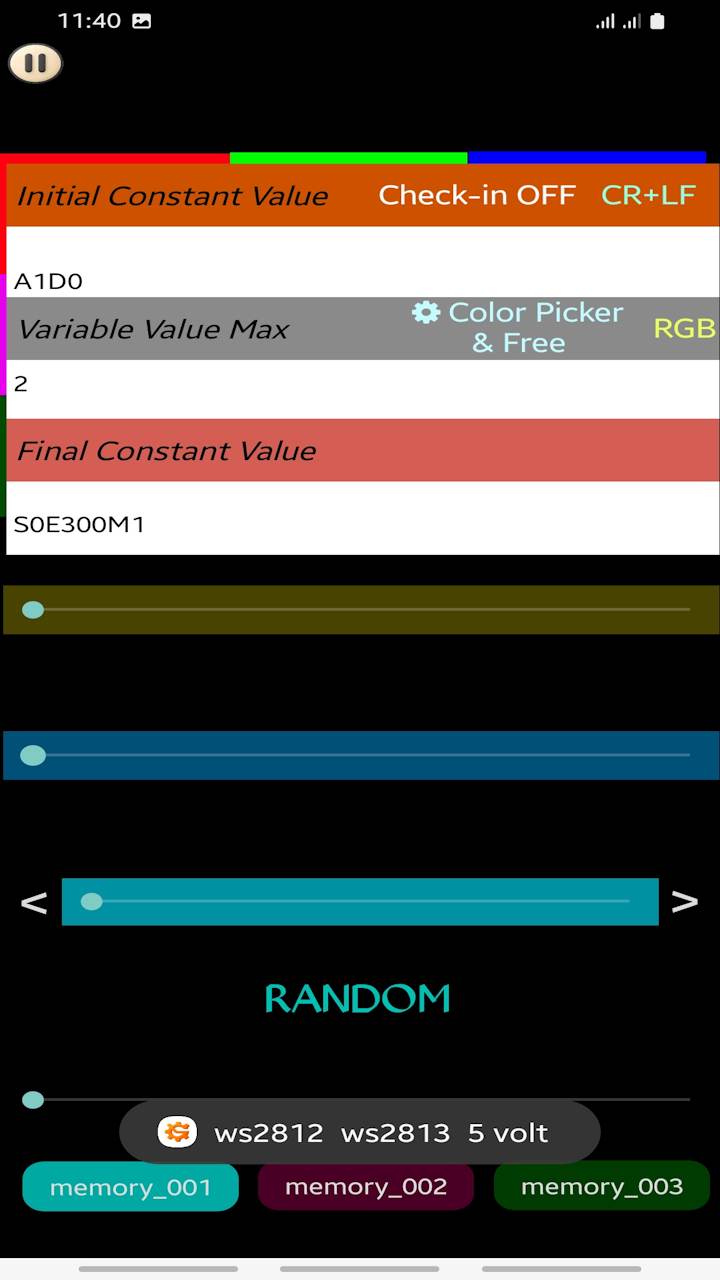
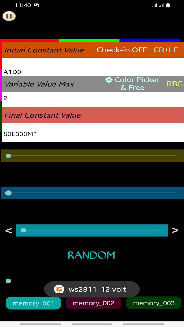
Color Swap Issue between WS2811 and WS2812: Why Green and Blue are Reversed When working with addressable LED strips like the WS2811 and WS2812, you might notice a classic issue: when you test your LEDs, the Red color displays perfectly, but Green and Blue are completely swapped. Why does this happen? While the Red channel remains in its correct first position, the order of the Green and Blue channels varies due to hardware layout designs: WS2812 LEDs typically use the internal GRB or standard RGB color ordering profile. WS2811 ICs are external controllers often used in 12V strips or pixel strings. To simplify PCB routing and prevent copper traces from crossing over each other, manufacturers frequently cross-wire the Green and Blue output pins to the LED. As a result, from a programmer's and user's perspective, the strip ends up behaving as an RBG (Red, Blue, Green) device instead of a standard RGB device. Why We Inverted the Logic in the Code (Under the Hood) To prevent any confusion or "color dizziness" while designing your light patterns, Soifgo handles all the heavy lifting behind the scenes. Most modern WS2811 strips available on the market today use an internal RBG chip methodology. However, to keep things intuitive for you, the app lets you think and work in the universal RGB standard. When you pick a color in the app—for example, setting R=123, G=22, B=12—you don't have to worry about the strip's internal layout. When the RBG mode is active: You interact with the familiar RGB values naturally. The microcontroller intentionally and automatically swaps the Green and Blue bytes right before transmitting them over the wire. The flipped data matches the physical cross-wiring of the WS2811 chip perfectly. In short, we deliberately inverted the software logic for the WS2811 setting so that your workflow remains simple, consistent, and strictly RGB on the screen, while the hardware gets exactly what it needs! Solution in Soifgo Settings If you are experiencing this color mismatch, there is no need to change your hardware wiring. You can fix this instantly via software inside the app: Important Note for Soifgo Users: When using certain WS2811 LED strips where the Green and Blue colors are reversed, simply go to the application settings and tap on the RGB label to switch it to RBG. By changing this setting to RBG, Soifgo will automatically swap the Green and Blue bytes during data transmission, ensuring that your color palette and light animations are applied accurately to your strip!
💻 Developer Note: Coding Static Colors for WS2811 If you are writing your own custom firmware or setting up static colors directly in your micro-controller code for a WS2811 strip, you must manually swap the Green and Blue values to achieve the correct output. Since the physical hardware layout of these strips interprets data differently than our standard mental model, you need to trick the strip by reversing the variables. For Example: If your desired color is Red: 10, Green: 123, Blue: 44, writing it in the standard order will result in swapped colors on the strip. To fix this in your code, you must pass the values like this: Standard RGB Intended Color: R: 10, G: 123, B: 44 Actual Code to Write for WS2811: R: 10, G: 44, B: 123 By intentionally swapping the Green (123) and Blue (44) values inside your code, the WS2811 strip will display the exact shade you originally intended!If you need the module as a single unit, you can use regular sockets. However, when using multiple modules in parallel, only the Bluetooth socket should be connected through long-pin headers so that the remaining modules can receive Bluetooth serial data. Next, it is better to mechanically connect the modules together using spacer screws. For the final module, you can insulate the pins or use a suitable cover. Alternatively, if you are certain that you will not expand the number of modules in the future, you may use short-pin headers instead.