
GIF209 v1.0
GIF209 is a professional, open-source hardware controller based on the STM32F030K6T6 ARM Cortex-M0 microcontroller. It is specifically designed to drive up to 19 independent WS2812/WS2811 LED strips and features standalone animation recording and playback via an SD card.
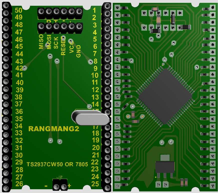
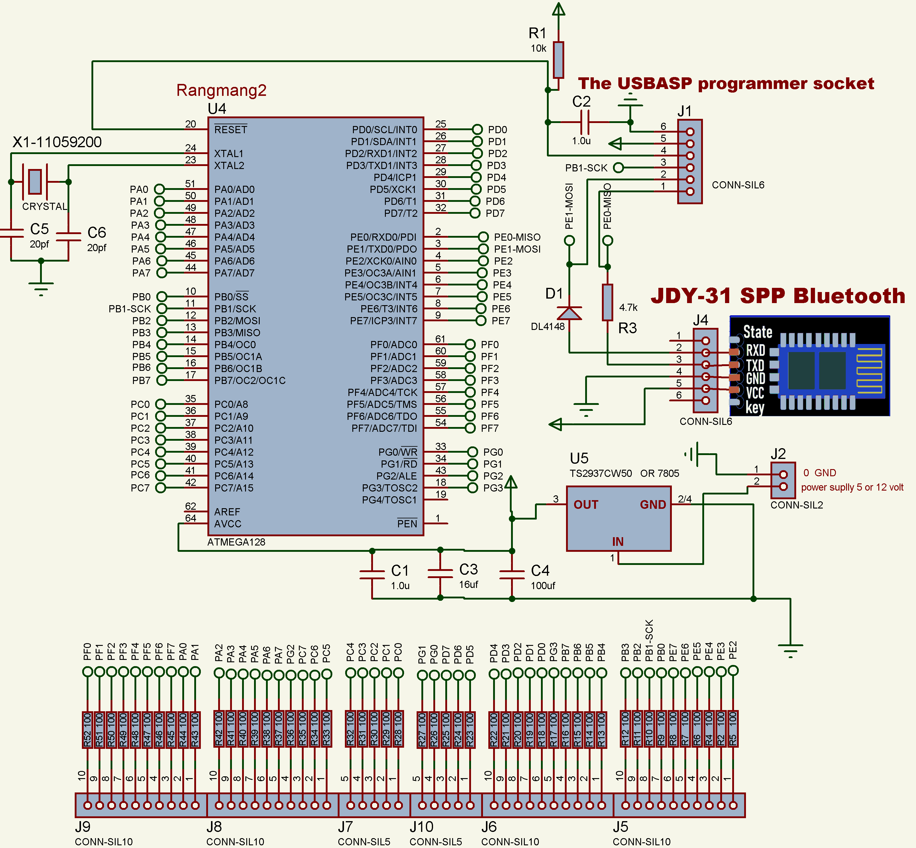
Hardware Specifications
| Feature | Specification |
|---|---|
| Microcontroller | STM32F030K6T6 (ARM Cortex-M0, 48 MHz, LQFP32) |
| Channels | 19 independent LED data lines (A1–A19) |
| Pixels per Channel | Up to 256 (Total 4,864 pixels) |
| Storage | SD Card via SPI1 (Raw access, no filesystem) |
| Communication | Bluetooth HC-05 (UART, 115200 baud; set the module with AT+UART=115200,0,0) |
| Supported LEDs | WS2812, WS2812B, WS2811, WS2813, WS2815 |
Pinout & Channel Map
Channels are mapped based on the physical pin number of the LQFP32 package (from pin 2 to 30) to make PCB routing easier.
- Channel 1–2: PF0 (Pin 2), PF1 (Pin 3)
- Channel 3–6: PA0 (Pin 6), PA1 (Pin 7), PA2 (Pin 8), PA3 (Pin 9)
- Channel 7–8: PB0 (Pin 14), PB1 (Pin 15)
- Channel 9: PA8 (Pin 18)
- Channel 10–11: PA11 (Pin 21), PA12 (Pin 22)
- Channel 12–13: PA13 (Pin 23), PA14 (Pin 24)
- Channel 14: PA15 (Pin 25)
- Channel 15–19: PB3 (Pin 26), PB4 (Pin 27), PB5 (Pin 28), PB6 (Pin 29), PB7 (Pin 30)
Reserved Pins:
- SD Card: PA4 (CS), PA5 (SCK), PA6 (MISO), PA7 (MOSI)
- Bluetooth: PA9 (TX), PA10 (RX)
- Boot jumper: BOOT0 (Pin 31), used for flashing (see below)
Command Protocol
Commands are sent via Bluetooth as plain text. Every line must end with a newline character (\n or \r\n). The controller acknowledges most commands with next for flow control.
1. Pixel Data (ARGBSE)
To control LEDs, send a 12-character hex string representing 6 variables:
A R G B S E
| Variable | Meaning | Range | Hex Range |
|---|---|---|---|
| A | Channel Address | 1 – 19 | 01 – 13 |
| R | Red Intensity | 0 – 255 | 00 – FF |
| G | Green Intensity | 0 – 255 | 00 – FF |
| B | Blue Intensity | 0 – 255 | 00 – FF |
| S | Start Pixel | 0 – 255 | 00 – FF |
| E | End Pixel | 0 – 255 | 00 – FF |
Example: 01FF00000005 sets Channel 1, pixels 0 to 5, to Red (FF0000).
2. Control Commands
| Command | Description | Response |
|---|---|---|
wait | Clears untouched channels (used as a frame separator) | next |
wait=N | Clears untouched channels and waits N milliseconds | next |
REC | Starts recording frames to the SD card | REC OK |
END | Stops recording and saves the header | SAVED n |
PLAY | Plays the recorded frames once | PLAY DONE |
LOOP | Plays the recorded frames continuously (loop) | STOPPED |
STOP | Stops playback or recording immediately | STOPPED |
AUTO=0 | Enables auto-loop on boot (Default) | OK AUTO=0 |
AUTO=1 | Disables auto-loop (waits for user command) | OK AUTO=1 |
ERASE | Clears the recording header (frames=0) | ERASED |
INFO | Shows current status (frames, channels, delay, auto) | frames=.. ch=.. |
DUMP | Sends raw data of all stored frames to terminal (for debugging) | HDR raw:... |
Web Application
The GIF209 Web App allows you to convert images or draw custom pixel art, and then generate the exact hex commands needed for the controller. It automatically handles the REC and END wrappers and formats everything perfectly.
🎞️ GIF import: drop an animated GIF into the app and it is split into frames automatically. Each frame becomes one line of commands, and the GIF frame delays can be converted to wait=N.
- Split GIF into frames: turns the GIF into one frame per line.
- Every Nth: keeps only every Nth frame to make long GIFs shorter (1 = all frames).
- Use GIF delays as wait: uses the delay of each GIF frame as
wait=N.
GIF splitting needs a browser with ImageDecoder support (Chrome or Edge). In other browsers the GIF is added as a still image.
Safety Warning
⚠️ Important Notice
1. The SD card is accessed in RAW mode. There is no filesystem (FAT32) on it. The controller will overwrite sectors starting around 2000. Always use a spare or blank SD card.
2. The STM32 operates at 3.3V logic. If you are using 5V LED strips (WS2812B), you must use a logic level converter (like 74HCT245 or 74HCT125) to prevent damaging the microcontroller.
Flashing the Firmware (Boot Jumper)
The two SWD programming pins (PA13 and PA14) are used as LED outputs on this board, so the firmware cannot be flashed or debugged through SWD. Instead, the STM32 built-in bootloader is used over UART (PA9 / PA10), and it only starts when the BOOT0 pin is held high during reset. This is the job of the BOOT jumper.
- Disconnect the Bluetooth module (it shares PA9/PA10), and connect a 3.3V USB-to-serial adapter: adapter TX to PA10 (RX), adapter RX to PA9 (TX), and GND to GND.
- Flash mode: connect (install) the BOOT jumper, then power the board or press reset.
- Flash
main.c(compiled) with a UART bootloader tool such as STM32CubeProgrammer (UART mode) or stm32flash. - Normal mode: remove the BOOT jumper, reconnect the Bluetooth module, and reset the board so the firmware starts.
Important: if the BOOT jumper stays connected, the board will enter the bootloader on every reset and the LEDs will not work. Always remove the jumper after flashing.
Downloads
Get the source code, PCB schematics, and the latest firmware updates from the repository.